Creating a Test Plan - SRRC 2.4G
The SRRC 2.4G option is used for China SRRC (State Radio Monitoring Center) type approval testing of micro-power products in the 2.4 GHz band. When creating a test plan, select the Type (technology) first: WLAN / Bluetooth / BLE / Proprietary. Each type is described separately below.
WLAN
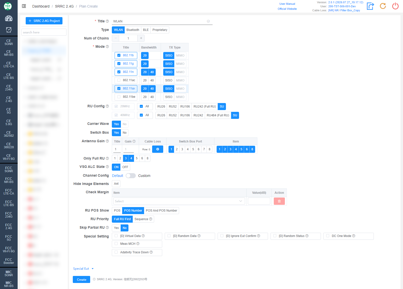
Title: Test plan name, entered by the user, e.g., WLAN / BT / WiFi-Ant1.
Type: Technical category, select WLAN here.
Num of Chains: Number of transmit chains (antennas) the product has.
Mode: Modes supported by the product (required): 802.11b / g / n / ac / ax / be. After checking a mode, select the corresponding Bandwidth (20 / 40 MHz) and TX Type (SISO / MIMO).
RU Config: RU (Resource Unit) configurations supported by 802.11ax / be devices. The Full RU of each bandwidth is required; select the other RU configurations according to the product's actual support. Displayed after 802.11ax / be is checked.
Carrier Wave: Whether the product supports carrier wave transmission. The SRRC carrier frequency tolerance may only be tested in carrier wave mode, so only Yes can be selected here.
Switch Box: Whether to use a Switch Box. If a Switch Box has not been purchased, select No, and the product will be directly connected to the spectrum analyzer for testing.
Antenna Gain:
Title: Antenna number, named sequentially by default as 1, 2, 3, 4..., or manually input other names according to customer requirements.
Gain: Gain of each antenna in the corresponding band (Band).
Cable Loss: Cable loss of the RF cable from the product's antenna port to the Switch Box (RF port of the switch) or the SA (spectrum analyzer). How to Create Common Cable Loss.
Switch Box Port: Port number of the switch connected to the product's antenna, e.g., Ant1 connected to port 1, Ant2 connected to port 2.
Item: Test items for each antenna; the numbers correspond as follows:
(S2401) EIRP
(S2402) E.I.R.PSD
(S2403) Operating Frequency Range
(S2404) Occupied Bandwidth
(S2405) Frequency Error (carrier frequency tolerance)
(S2406) Conducted Spurious Emission
(S2408) Adaptivity (Channel Access Mechanism)
The software preselects the default test items according to the characteristics of each technology. Note: In some cases, test parameters are mutually referenced between items; it is recommended to create the test plan with the default items.
Bluetooth
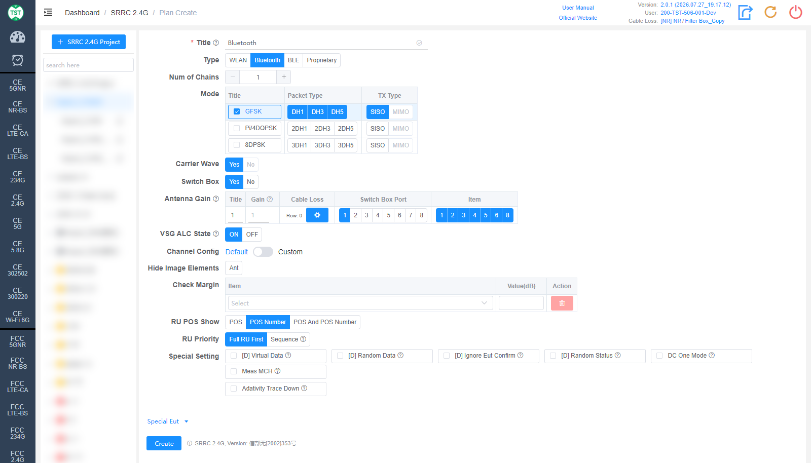
Type: Technical category, select Bluetooth here.
Num of Chains: Number of transmit chains the product has; Bluetooth currently supports only a single antenna.
Mode: Modulations and packet types (Packet Type) supported by the product: GFSK (DH1/DH3/DH5), Pi/4DQPSK (2DH1/2DH3/2DH5), 8DPSK (3DH1/3DH3/3DH5).
Carrier Wave / Switch Box / Antenna Gain are the same as WLAN and are not repeated here.
BLE
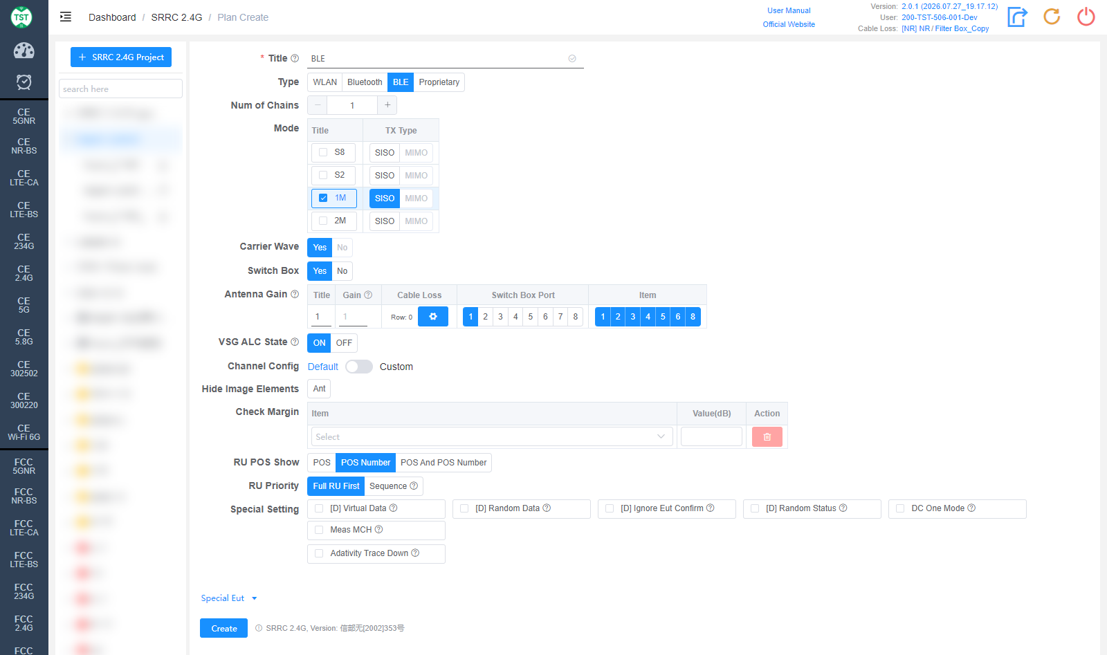
Type: Technical category, select BLE here.
Num of Chains: Number of transmit chains the product has; BLE currently supports only a single antenna.
Mode: Modes supported by the product: S8 / S2 / 1M / 2M. In protocol versions before BT 5.0, BLE only had the 1Mbps rate. Starting from version 5.0, in addition to keeping the 1Mbps rate, two new rates for Long Range scenarios targeting IoT products, S8 and S2 (corresponding to 125kbps and 500kbps respectively), were added, along with the 2Mbps rate for high-bandwidth scenarios. Among them, the 1Mbps rate is mandatory for version 5.0 and above, while the other three rates are optional. S8 and S2 are implemented by adding FEC (Forward Error Correction) on top of 1Mbps; the symbol rate is still 1Mbps, and the actual test results are basically identical to 1M. Therefore, for products that support all three rates, generally only the 1M mode is tested.
Carrier Wave / Switch Box / Antenna Gain are the same as WLAN and are not repeated here.
Proprietary
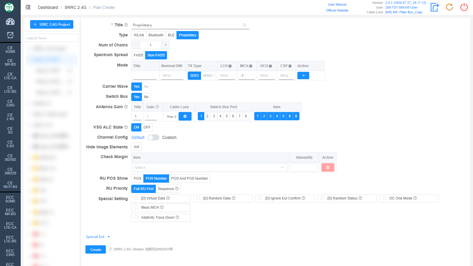
Type: Technical category, Proprietary (custom product).
Num of Chains: Number of transmit chains (antennas) the product has.
Spectrum Spread: Select the spectrum spreading method:
FHSS: Frequency Hopping Spread Spectrum, which transmits the signal by rapidly switching (hopping) among a set of known frequencies, thereby spreading the signal over the spectrum.
Non-FHSS: Non-frequency-hopping method.
Mode: Custom mode table:
Title: Mode number; other names can be manually input according to customer requirements.
Nominal BW: Sets the nominal bandwidth occupied by the signal on the spectrum.
TX Type: Transmission type, SISO / MIMO.
LCH / MCH / HCH: Low / middle / high channel frequency settings (MHz).
CSP: Channel Spacing.
Action: Used to add / delete mode configuration rows.
Carrier Wave: Whether the product supports carrier wave transmission. The SRRC carrier frequency tolerance may only be tested in carrier wave mode, so only Yes can be selected here.
Switch Box / Antenna Gain are the same as WLAN and are not repeated here.
Advanced Setting and Special Eut Settings
The following settings can generally be kept at their default values. Adjust them only when the test results are abnormal or there are special test requirements.
VSG ALC State: Power ALC (Automatic Level Control) state of the vector signal generator (ON / OFF). When ALC is ON, the signal generator automatically adjusts the output level to compensate for output power drift caused by temperature changes, signal attenuation and other factors; when OFF, it no longer adjusts actively. Used for the Adaptivity test.
Channel Config: Channel configuration, Default or Custom (manually customized channels).
Hide Image Elements: Select the elements to hide in report images (e.g., the Ant antenna marker).
Check Margin: Test margin check. Select an Item and fill in Value(dB); when the margin between the test result and the limit is smaller than the set value, the system will flag it.
RU POS Show: How the RU position is displayed in the report: POS / POS Number / POS And POS Number.
RU Priority: RU test priority: Full RU First or Sequence (in the order RU26 → RU52 → RU106...).
Special Setting: Special settings. Options prefixed with [D] are debug options and do not need to be checked for normal testing:
[D] Virtual Data / [D] Random Data / [D] Ignore Eut Confirm / [D] Random Status: Debug options.
DC One Mode: Only one duty cycle is tested per mode, e.g., 802.11b only measures the duty cycle of the LCH.
Meas MCH: Whether to measure the middle channel. By default SRRC only measures the LCH and HCH; if the customer has a special requirement to measure the MCH, simply check this option.
Adativity Trace Down: Option to shift the trace display down for the Adaptivity test.
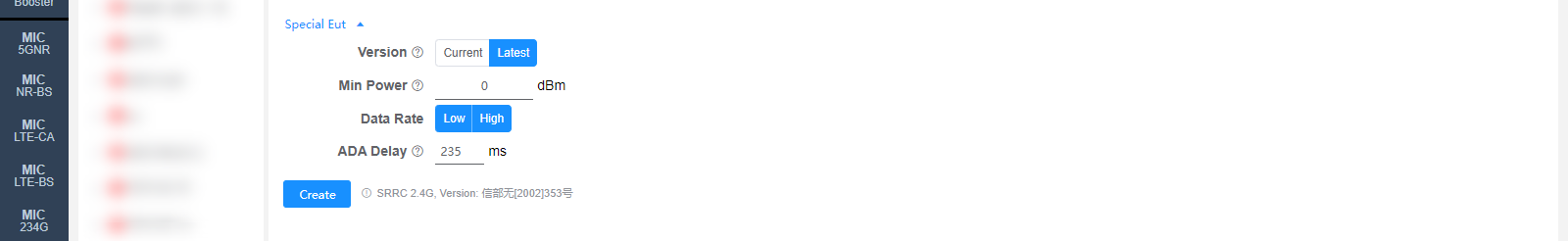
Version: Select the regulation version: Current / Latest. The default value can be changed on the Setting page.
Min Power: Sets the minimum power (dBm); 0 means automatic.
Data Rate: Data rate, multi-select: Low (low rate) / High (high rate).
ADA Delay: Delay (ms) for the Adaptivity test. The default value can be changed on the Setting page.
Corresponding software option: SRRC 2.4G